

We’re committed to providing you with informative and accessible articles about all things slurry, from pump performance and real-world applications to troubleshooting and theory. In case you missed a post, or just need a little review, we compiled an overview of some of our subscribers’ favorite blogs related to slurry transport.
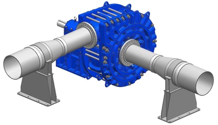
Stress from piping
Centrifugal pump systems are subject to a variety of pressures and forces, called loads. The magnitude and direction of forces acting on the pump depend on the operating conditions, discharge position, and piping layout. In general, there are two categories of loads — hydraulic loads and allowable flange loads. Hydraulic loads are fluid pressure and internal momentum loads, which are determined by operating conditions (e.g., flow rate, pressure, effective diameter, slurry-specific gravity). Allowable flange loads are external forces and related to the piping itself. The allowable flange loads are based on standards established by the Hydraulic Institute and can be found in the Maintenance Manual and on the General Arrangement drawings.
When it comes to the piping, several parts can impact the pump due to weight, thermal expansion, misalignment, and axial loads. The parts affected include:
- Diffusers: Diffusers can cause the loads on the pump’s discharge flange to increase. This occurs when the diffuser is not supported and is used in conjunction with a Flexible Victaulic coupling that allows for pipe movement. Since the pipe diameter is larger than the pump nozzle inner diameter, the larger pressure area creates a force that pushes back on the pump flange.
- Pipe Couplings: These grooved-end couplings have raised edges that fit securely into the lower edge of the coupling and bolt onto both sides of the piping. These couplings can be flexible or rigid, depending on the system’s requirements; grooved-end pipes are compatible with both styles.
- Flexible Couplings: These couplings are designed to accommodate the axial movement that may occur during startup. Although some rigidity still exists, the piping will generally no longer support any hydraulic load. Rather, all of the hydraulic load is transferred to the pump foundation and/or pipe supports, depending on pipe support design and location.
- Rigid Couplings: In contrast to flexible couplings, rigid couplings carry a portion of the hydraulic load. KSB GIW, Inc. estimates that, with rigid couplings, piping carries 50% of the hydraulic load. The remainder of the loads are carried by the pump foundation. Operators should not rely on these couplings to support axial movement.
- Pipe Support: These are key to reducing the loads carried by the pump itself. The allowable load standards defined by KSB GIW, Inc. assume sufficient pipe supports and stiffness such that the hydraulic load is split evenly between the pump and the piping. By placing pipe supports close to the flanges, operators can be sure that the loads acting on the pump flange will be lower. Therefore, they should design the layout of their pump system in such a way that flange loads remain lower than KSB GIW, Inc.’s allowable loads. Exceeding these loads can result in equipment damage.
Operators should note that the pump itself should never be used as piping support. This can add stress to the system and risk damage. To avoid this, ensure all loads — including those from couplings and diffusers — are properly supported.

Pipeline flow measurement
Measuring a pipeline’s flow rate is a critical part of pump operation. To do this, operators have a few tools at their disposal, including magnetic flow meters, Doppler meters, and sonar flow meters.
- Magnetic flow meters: Some consider these to be the most dependable of the three. They are installed within a section of the pipeline, and measure the velocity of liquids and solids in the line to determine flow. These operate best in upward-flowing pipes, but can be used reliably in horizontal lines as well.
- Doppler meters: These act like a stethoscope outside the pipe, and measure slurry velocity using ultrasonic pulses. These can be difficult to use, as they are highly sensitive to sound, and must be calibrated for each type of slurry.
- Sonar flow meters: These “listen” to flow and measure velocity with acoustic sensors outside the pipeline. They are almost as accurate as magnetic flow meters but can be less accurate in slower slurry pumping velocities.

Vane pass
Vane pass refers to the pressure pulsations generated in the pump as the impeller vanes pass the cutwater. Operators measure vane pass frequency and amplitude to determine its impact. Vane pass frequency refers to the rate at which the rotating vane passes the cutwater, while amplitude refers to the magnitude of the pressure pulsations in one pass.
Operators should be wary of high vibration as it can lead to damage, especially if the vane pass frequency is close to the natural frequency of a part in the system. Other problems associated with vane pass may include:
- Torsional-resonance in the drive train, which can lead to over-stressing and fatigue failure in the rotating assembly;
- Baseplate and/or foundation resonance when foundations are unstable due to poor support, too flexible or too light; and
- Piping resonance when piping arrangement are under-supported.
Owners of vertical pumps should be aware that these types of pumps are especially vulnerable to vibration problems.
Fortunately, there are several ways to reduce the impact of vane pass amplitude and the resulting vibrations, including:
- Selecting pumps carefully to ensure the operating conditions are within optimal range for the best efficiency point flowrate (BEPQ).
- Avoiding three-vane impellers for high head applications.
- Minimizing the head per pump stage by adding booster pumps or reducing system resistance.
- Supporting all components of the pump system to minimize the effect of resonance associated with vane pass.
When it comes to making your pump last, knowledge and care go a long way. Keep these slurry transport tips in mind when operating your pumps. And, if you need additional pump expertise and support, KSB GIW, Inc. is always here to help!