Operators in the mining industry are aware that centrifugal pump systems are subject to pressures and forces. To minimize stress and lower the risk of damage, customers should educate themselves about these loads, how they can impact their systems, and how to counteract them with the help of pipe supports and good design.
Pipe support basics
The magnitude and direction of forces acting on the pump depend on the operating conditions, discharge position, and piping layout. There are generally two categories of loads to account for:
- Hydraulic loads: Also called nozzle loads, these refer to fluid pressure and internal momentum loads. They are determined by operating conditions, including flow rate, pressure, effective diameter, and slurry specific gravity.
- Allowable flange loads: These are generally the external forces that act on the pump flanges. This includes the weight and thermal expansion of the attached piping, piping misalignment, and axial loads related to increased pipe diameter upstream or downstream of the pump.
The allowable flange loads are based on standards established by the Hydraulic Institute, and can be found in the Maintenance Manual and on the General Arrangement drawings. KSB GIW, Inc. pumps are often capable of exceeding these standards. If a customer’s loading conditions exceed the standard allowable flange loads, then an FEM analysis must be requested. The analysis will determine suitability of the design for the proposed loading.
To isolate pumps from piping loads, operators must carefully account for all loads in the system and should install supports at key locations. Failure to do so can result in damage to the system components. Although this is true for all pumps, forces can be especially powerful in multi-stage and high-pressure slurry pumps in series.
Forces on systems
To design pump systems properly, operators must understand loading generated by piping. Let’s take a closer look at the effects of piping on pumps, part by part:
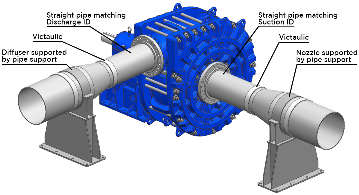
- Diffusers: Diffusers can cause the loads on the pump’s discharge flange to increase. This occurs when the diffuser is not supported and is used in conjunction with a Flexible Victaulic coupling that allows for pipe movement. Since the pipe diameter is larger than the pump nozzle inner diameter, the larger pressure area creates a force that pushes back on the pump flange.
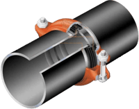
 Pipe Couplings: These grooved-end couplings have raised edges that fit securely into the lower edge of the coupling and bolt onto both sides of the piping. These couplings can be flexible or rigid, depending on the system’s requirements; grooved-end pipes are compatible with both styles.
- Flexible Couplings: These couplings are designed to accommodate the axial movement that may occur during startup. Although some rigidity still exists, the piping will generally no longer support any hydraulic load. Rather, all of the hydraulic load is transferred to the pump foundation and/or pipe supports, depending on pipe support design and location.
- Rigid Couplings: In contrast to flexible couplings, rigid couplings carry a portion of the hydraulic load. KSB GIW, Inc. estimates that, with rigid couplings, piping carries 50% of the hydraulic load. The remainder of the loads are carried by the pump foundation. Operators should not rely on these couplings to support axial movement.
- Pipe Supports: These are key to reducing the loads carried by the pump itself. The allowable load standards defined by KSB GIW, Inc. assume sufficient pipe supports and stiffness such that the hydraulic load is split evenly between the pump and the piping. By placing pipe supports close to the flanges, operators can be sure that the loads acting on the pump flange will be lower. Therefore, they should design the layout of their pump system in such a way that flange loads remain lower than GIW’s allowable loads. Exceeding these loads can result in equipment damage.
Preferred pump arrangement and supports
As a key step in designing pump layout, pipe support placement can be a daunting exercise. Fortunately, customers have KSB GIW, Inc.’s documentation on preferred piping arrangement at their disposal, including diagrams:

Here are some final tips to consider when designing the layout of pipe supports:
- The pump should never be used as piping support. Rather, supports should be placed near the pump to minimize the impact of the piping loads.
- Any loads created by couplings — including diffusers, nozzles, oversized piping, and grooved pipe couplings (also known as Victaulics) — must have sufficient support. Failure to support these parts can result in damage to the system.
- High-pressure pumps in series are at greater risk of damage than other types of pumps. Customers operating these pumps must ensure their system has enough support.
When designing a pump system’s layout, it is crucial for operators to account for the types of loads that can affect the pump. Certain parts, such as couplings and supports, can increase or decrease the impact of loads. To minimize the risk of damage, customers should abide by KSB GIW, Inc.’s load standards, and consult an expert if they doubt their design.
