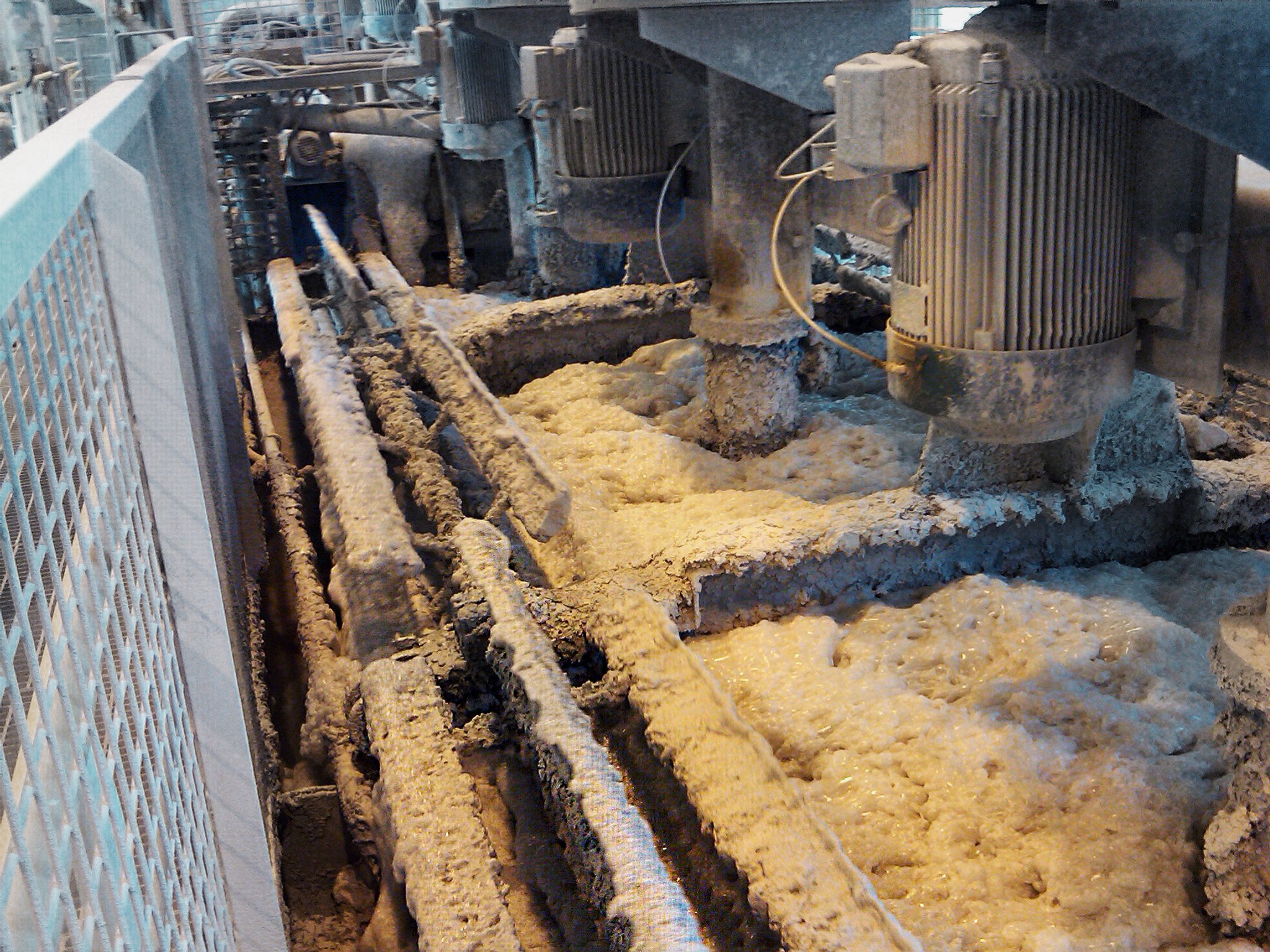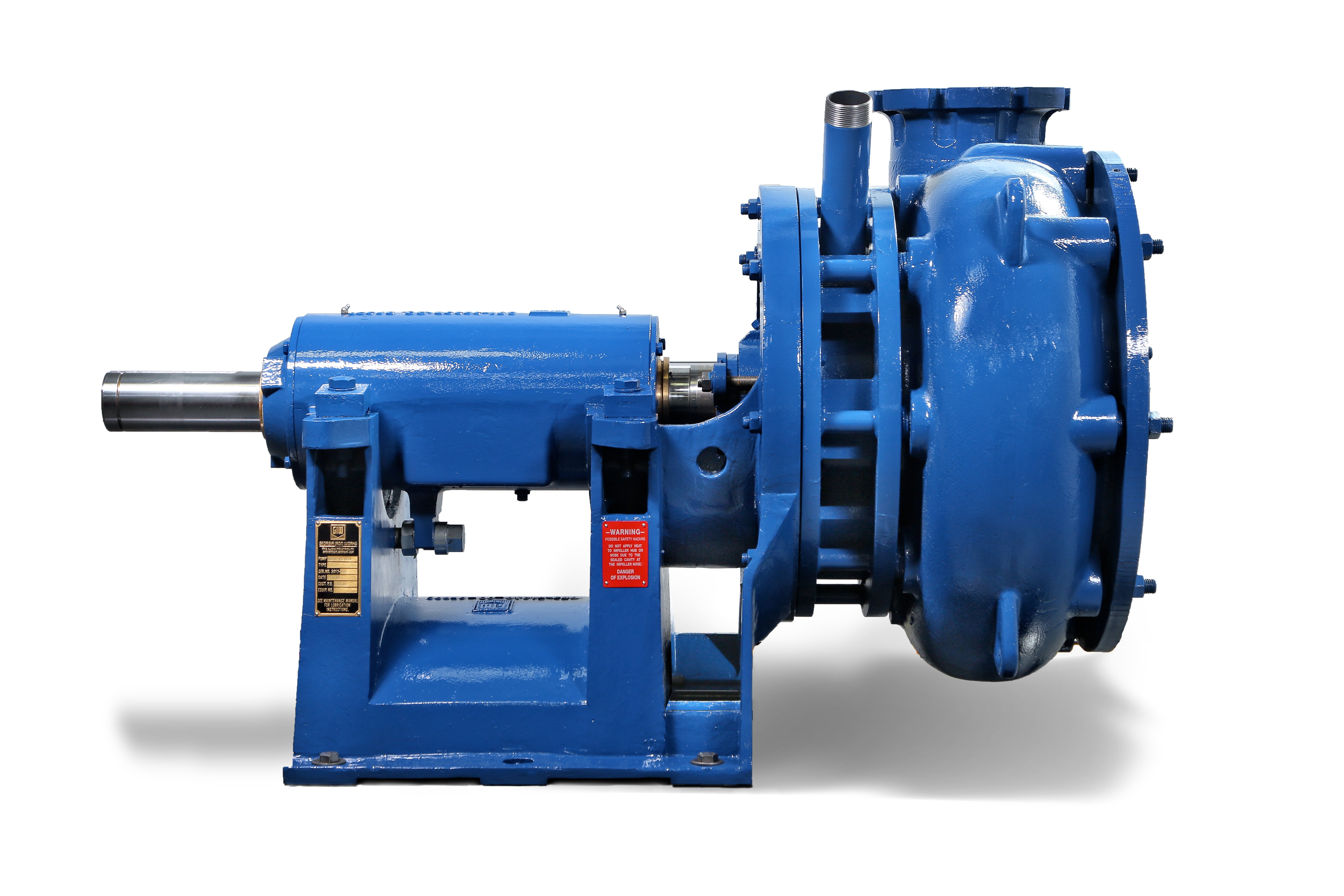
When it comes to extracting materials from a slurry, the method of extraction can have as many consequences as it does advantages. In some processes, air is injected into the slurry, which separates the desired materials (such as ore) from the discardable liquid. Froth applications can be challenging for conventional horizontal suction end pumps. It is not uncommon for the aeration to result in airlock at the suction eye of the pump, causing reduced or complete stoppage of flow. Fortunately, airlock can be avoided with a little engineering and help from KSB GIW, Inc.
The problem: airlock
In the case of processes that incorporate froth, the trouble begins when the air bubbles within the froth build up near the pump entrance. This is due to the pressure difference between the slurry liquid — which the pump expels at a high pressure — and the pump entrance; the air doesn’t move from the low-pressure impeller eye, effectively “locking” it near the entrance. This normally reduces flow, and therefore production — but if the airlock is severe enough, it can stop production entirely. Moreover, it only takes a little air to make a big impact in the form of lost time and money.
For example, a phosphate plant in Finland struggled with airlock following an upgrade to its facilities. The operators found they could only run their froth pumps at 115 m³/hour (about one third of the design specifications). Any higher, and the resulting airlock would cause sump overflow.
There are some remedial, reactive measures operators can take against airlock. Operators may slow down the process and limit the buildup of air; they may change the process liquid’s chemical composition; or, in some cases, they may pop the air bubbles manually. However, these methods add time and complexity to the pump operation, and they only treat the symptoms of airlock rather than the root cause.

The solution? The GIW HVF Pump
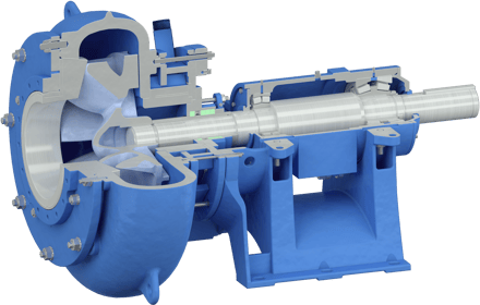
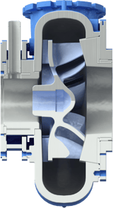
To solve the root cause of airlock, the KSB GIW, Inc. team developed the High-Volume Froth (HVF) pump. The HVF pump addresses each challenge of pumping froth with a special impeller design that has small holes in its center. Air from the froth goes through the holes and into a de-aeration chamber. Then the air, along with any fluid caught in the process, escapes and is redirected to the sump tank.

For KSB GIW, Inc. engineers, solving the froth problem included two steps. First, they had to fundamentally rethink how air bubbles interacted with the pump, especially in viscous slurries like oil sands. To simulate the oil sands’ thick bitumen and froth, the engineers created a solution of corn syrup and dish soap and tested it in GIW’s Hydraulic Lab; this helped them better understand the physics of the froth problem.
 Second, they had to retool certain pieces of KSB GIW, Inc. equipment. The HVF pump’s unique impeller design is completely different from any other impeller offered by the company. GIW’s industrial casting engineers had to translate the design into a manufacturable, wear-resistant product.
The development process was worth it. Once applied to a customer’s froth application, HVF operators experienced reduced downtime, decreased risk of sump overflow, and maximized capacity.
You may wonder: What happened to the phosphate plant in Finland? After contacting KSB GIW, Inc., they installed an HVF pump to handle their airlock problems. The operators soon found that they could run the pumping process at up to 450 m³/hour — far exceeding expectations — and without any risk of airlock!
